Measuring principle:Measurement of thermal conductivity
Measurable component:He, Ar, H2, CH4, CO2
Measurable range:Refer to Table 1
Outputsignal:4to20mADC,0to1VDC,0to10mV
DC
Isolated output
(Any one-output signal specifiable in CODE SYMBOLS)
Allowable load resistance:550 Wmax. (in 4 to 20 mA DC output)
Output resistance:100 kW(in 0 to 1 V DC or 0 to 10 mV DC output)
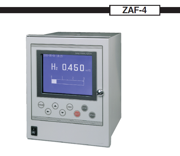
Displayunit:LCD withbacklight
Display of measured value:Max. 4 digits
Display language:English
Output signal holding:Inbothmanualandautomaticcalibrations, output value just before calibration can beheld.
Powersupply:100 to 240 V AC, 50/60Hz
Power consumption:Approx. 50 VA Warm-uptime: At least 30 min Ambienttemperature:
–5 to 45˚C
Ambient humidity:Less than 90% RH (condensation unal- lowable)
Storage conditions:–20 to 60˚C, less than 95% RH (conden- sation unallowable)
Mounting:Flush mounting onpanel
 Ða=90°
External dimensions (H x W x D):240 x 192 x 213 mm
Mass:Approx. 5kg
Finishcolor:Off-white (equivalent to10Y7.5/0.5)
Housing:Steel-plate case, indoor usetype
Material of gas-contacting parts:JIS SUS304, platinum, platinum iridium, silver, fluororubber, epoxy resin, nickel, tin
Gas inlet/outlet, purge port:Rc1/4 or NPT1/4 (whichever specified)
External connection terminal:M3.5 screw terminal (9-pin D-sub connec- tor for RS-232C)
Purge gas flow rate:Approx. 1 L/min (for measurement of combustible gases)
Table 1: Measurable Component and Measurable Range
|
Measured gas |
Reference gas component (Note 1) |
Measurable range |
Range ratio(Note 2) |
|
H2 |
N2, (CO2, Ar, He) |
0 to 3, 5, 10, 20, 50, 80, 100% 100 to 90, 100 to 80% |
1 : 10 |
|
He |
N2, (CO2, Ar) O2, Air |
0 to 5, 10, 20, 30, 40, 50, 80, 100% 100 to 90, 100 to 80% |
1 : 10 |
|
Ar |
N2, O2, Air, (He) |
0 to 10, 20, 50, 80, 100% 100 to 90, 100 to 80% |
1 : 5 |
|
CH4 |
N2, (CO2, Ar, He) |
0 to 20, 40, 50, 60, 80, 100% 100 to 80% |
1 : 5 |
|
CO2 |
N2, O2, Air, (He) |
0 to 10, 20, 50, 100% 100 to 90, 80% |
1 : 5 |
(Note 1) Contact us for the components in the parentheses. H 2 contained in O 2 cannot be measured.
(Note 2) Range ratio stands for maximum value.